Gesture Controlled Robot
My project is the Gesture Controlled Robot. The robot is a car that can be controlled with gestures performed on a gauntlet that rests on your hand. Whenever you tilt the gauntlet forwards, backward, right, or left, the robot moves correspondingly. A modification that I added lets me control a robotic arm on the front of the car to pick things up. The arm is also controlled on the gauntlet, but instead of tilting, it is controlled by joysticks.
| Engineer | School | Area of Interest | Grade |
| Joshua L | Leigh High School | Mechanical Engineering | Incoming Sophomore |
Modification
Description
Since my third milestone, I have attached a robotic arm to the top of my robot. For the first two days, I worked on constructing the hardware of the robotic arm and wiring the joysticks to the NANO shield. Afterwards, I spent a week debugging the Bluetooth connection and coding the robotic arm’s movement while also creating a 3D-designed mount that goes on top of the original robot. The robotic arm is mounted onto the gesture-controlled robot, which benefits the arm’s mobility and the gesture-controlled robot’s ability. Without being mounted onto the gesture-controlled robot, the robotic arm is stationary with little to no mobility. This restricts the capability of the arm to a 6-inch radius of reach, unlike an unlimited reach with the gesture-controlled robot.
Challenges
I faced many challenges incorporating the robotic arm into the gesture-controlled robot, but the two biggest challenges were the Bluetooth connection and broken pieces. When I first tried to connect my Bluetooth from the joystick to the arm, I didn’t realize that the HC-O5s I was using were faulty. The HC-O5s would not connect even if I set them in the correct master-slave relationships. But luckily, after swapping the HC-O5s out and watching a tutorial for the connection, the Bluetooth connection worked flawlessly. It turned out the HC-O5s were broken, but I was also mixing up the CMODE and ROLE commands in AT mode. The other challenge that I faced was two broken pieces. When I was trying to reset one of my servos to 90 degrees, two parts connecting the arm to the base snapped off. This stopped me from attaching the robotic arm to the gesture-controlled robot and delayed everything when I only had three days left. Another small challenge that I faced was stripped screws. When mounting the robotic arm onto my 3D printed design, I stripped two screws, so I had to drill some new holes.
What’s Next?
Next up is my demo night presentation, where I will demonstrate how my project works, what I learned, and the challenges I’ve faced.
3D Robotic arm modification
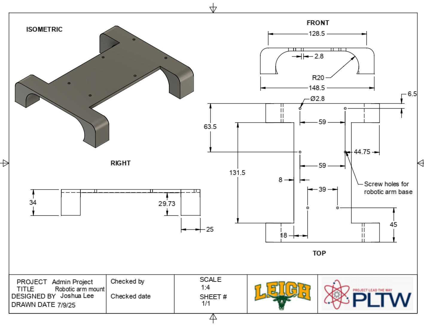 Figure 1: Design drawing of my robotic arm mount
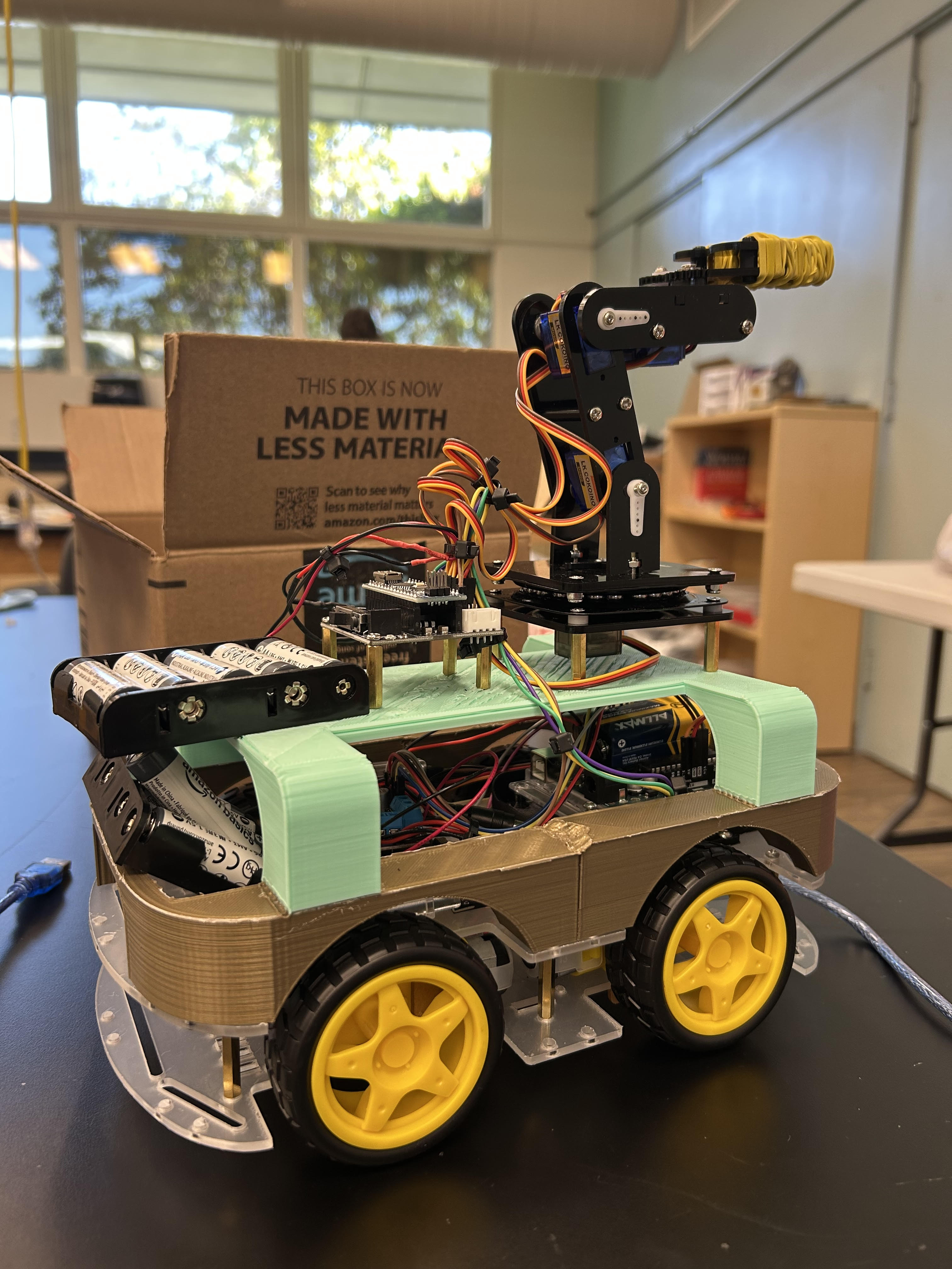 Figure 2: Image of the completed project
How it works
Servos (MG90S)
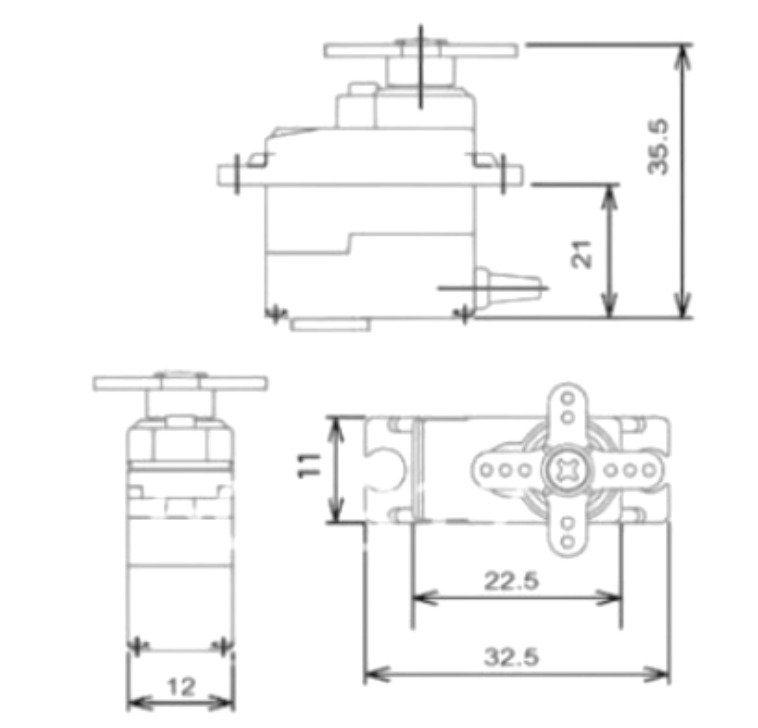 Figure 3: Diagram of an MG90S servo
This servo contains four different components: a DC motor, a gearbox, a control circuit, and a potentiometer. The DC motor is the primary component that provides the mechanical power for rotation, and the gearbox is a series of gears that reduce the motor’s speed while increasing torque, allowing for precise movement in degrees. Additionally, the control circuit is the brain of the servo. It receives signals from an external controller, in this case the NANO, processes them, and then determines the position, speed, and torque required for the motor shaft. Lastly, the potentiometer acts as a feedback mechanism, monitoring the motor’s current position and reporting it back to the control circuit. The servo uses all of these components to determine how it should move.
Joystick
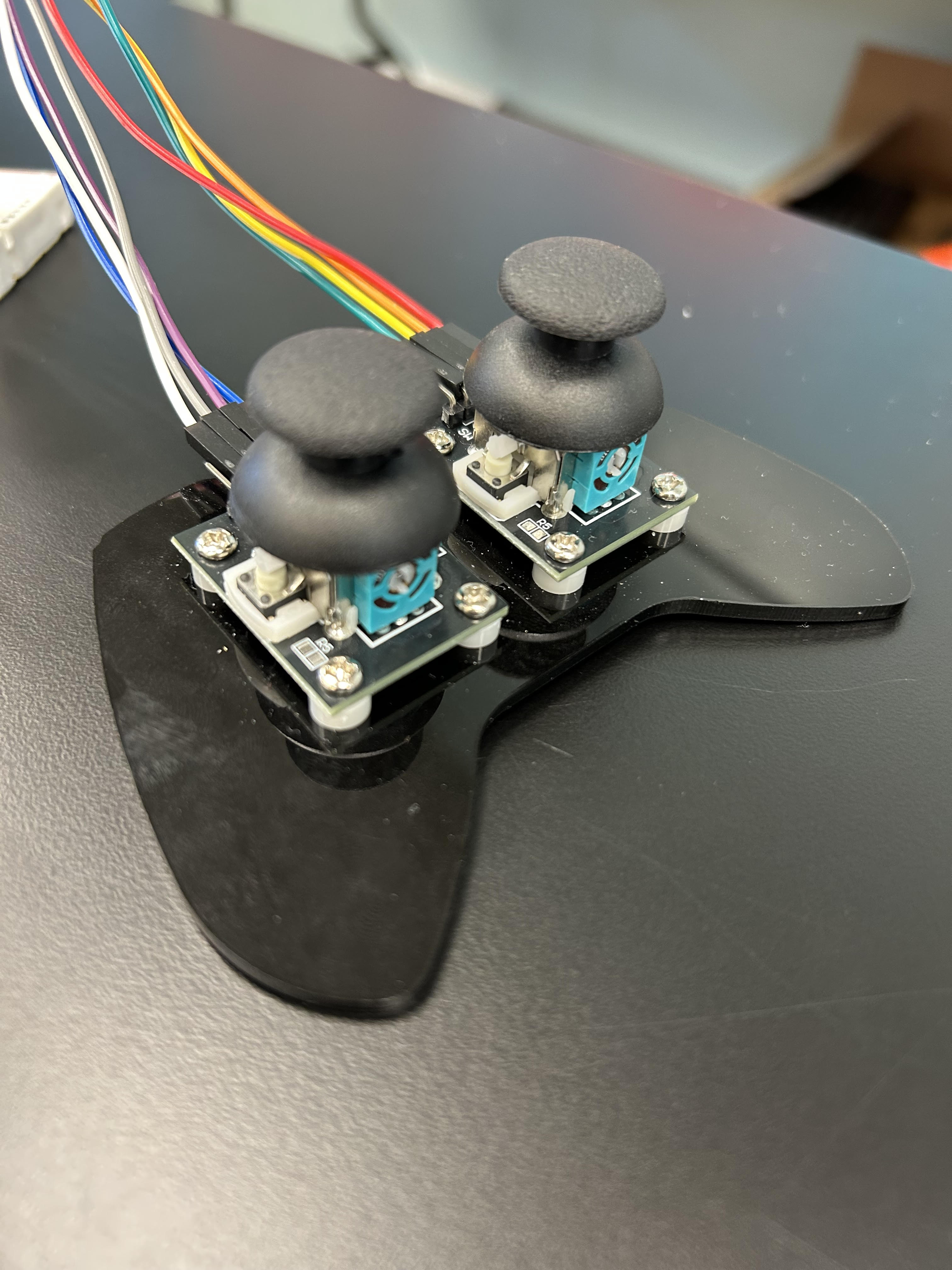 Figure 4: Image of the joystick in my project
The joystick consists of three different components: a potentiometer, a handle, and a centering mechanism. A potentiometer is the core of the joystick module. There are two potentiometers mounted at 90-degree angles to each other. One potentiometer handles movement along the X-axis (left/right), and the other handles movement along the Y-axis (up/down). Next, the handle is a physical stick that is connected to the potentiometers. Moving the handle causes the wipers of the potentiometers to move, changing their resistance. The change in resistance is then read by the analog pin, which is how the position of a joystick is determined in a computer. Lastly, the centering mechanism springs the joystick into the resting position, which is how it always returns to its original position. The joystick uses all these components to function and relay information about its position to a computer.
Final Milestone
Description
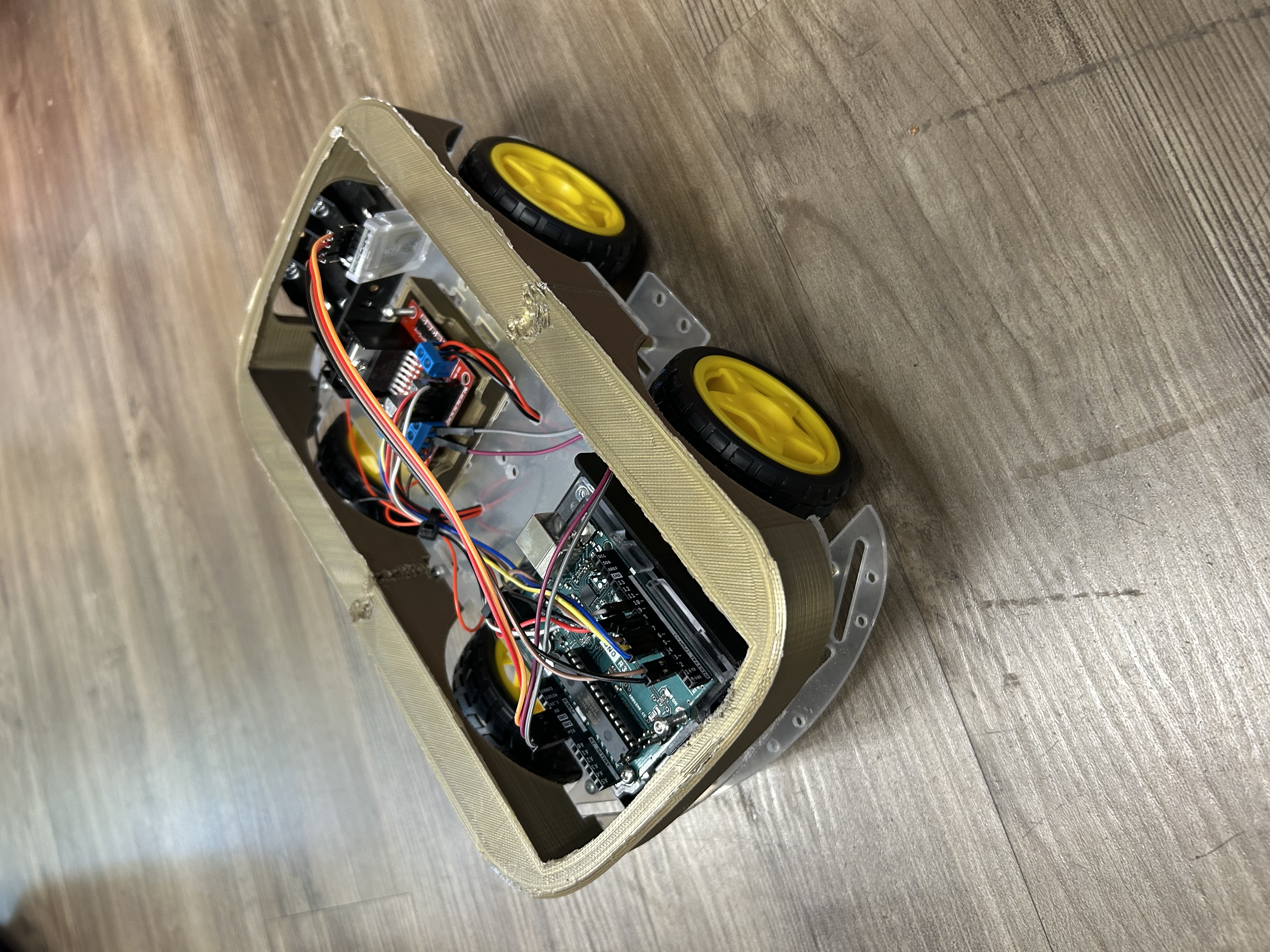
This is the final milestone of my project, excluding the modifications, and it turned out well. Since my previous milestone, I have 3D printed cases for my circuit boards so they attach to the base. The reason for this is that they would keep sliding around, and these 3D cases hold them in place. Furthermore, I was able to 3D print a frame that encases the robot. To incorporate this into my robot, I plastic-welded the joints (as seen in Figures 5 and 6) so they stuck together nicely. The plastic welding process starts with a soldering iron to heat both sections until they melt into each other. Then, you would have to use buffering tools to create a clean finish. The frame will let me attach modifications on top of the car and hide all the wires inside.
Since this is the last regular milestone of my project, I will explain how my gesture-controlled robot works. The first step to this is understanding the drivetrain. The drivetrain consists of four components: the base, motors, wires, and wheels. The motors are attached to the base plate and have two soldered wires - one positive and one negative - which are connected to the four ports on the right and left sides of the L280N. These are the input ports that enable the motors to be programmed through simple high/low commands(as shown at the bottom of the website).
The L280N is crucial for the robot’s functionality, which brings us to the second major system, the circuit boards. My project includes one L280N, one Arduino UNO, one MPU-6050, and one NANO board. Each circuit board controls its sector of my project, but they interact in unique ways. For example, the movement of the car is controlled by four main boards. The Arduino UNO, L280N, NANO, and MPU-6050. Both the UNO and L280N boards are located on the Gesture-controlled robot’s drivetrain, while the MPU-6050 and NANO boards are situated on a separate console. The reason for this is that the MPU-6050 is what makes my project “gesture-controlled,” and it is wirelessly connected to the robot so it can read the tilt of someone’s hand. This tilt information is processed by the NANO and sent to the UNO board, which sends the data to the L280N. The L280N then takes in the data to control the motor movement.
Another important part of this project is Bluetooth. The Bluetooth allows wireless communication, and in my project, I used 2 HC-O5s to communicate via Bluetooth (explanation of an HC-O5 shown in Figure 6). One HC-O5 is wired to the Arduino UNO, and one is connected to the NANO. The HC-O5 wired to the NANO board sends the information of the accelerometer over to the HC-O5 on the UNO board, which then runs it through the code. The resulting data is then sent over to the L280N (through analog), and the motors move in a direction depending on the data sent over.
This whole process is happening simultaneously and is how the gesture-controlled robot functions.
Challenges
A challenge I faced was when I was putting on the frame of the robot. The orientation of the Arduino UNO case was positioned in a way so that the ports were not accessible when I put the frame on. So, I turned the UNO case around, but I had a new problem: the frame didn’t fit. Luckily, after filing the UNO case, the frame fit in its place.
What’s Next?
Now that I have finished the non-modified robot, I will spend the rest of my time on modifications such as a robotic arm and LEDs.
CAD 3D Designs
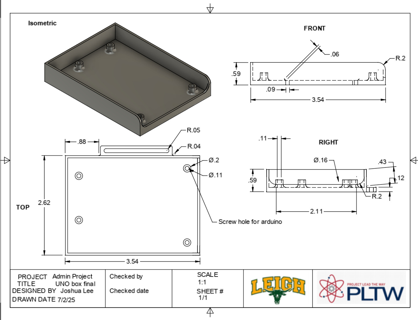 Figure 5: Design drawing for Arduino Case
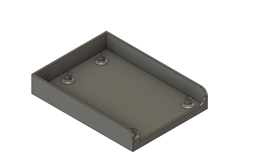
Figure 6: Case for the Arduino UNO - screw holes go through the lip on the right side of the case.
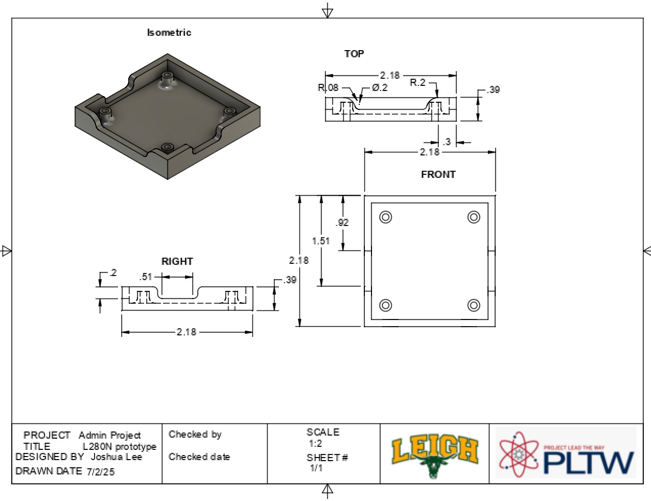 Figure 7: Design drawing for L280N case
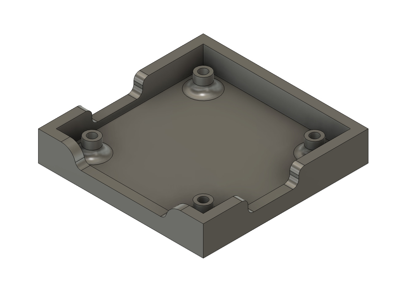
Figure 8: Case for the L280N - dips on the right, left, and front allow the wires to pass through.
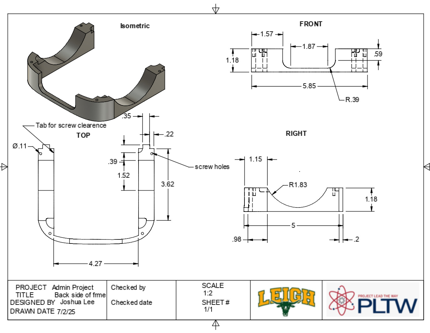 Figure 11: Design drawing of the back part of the frame
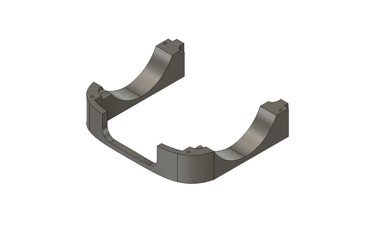
Figure 9: This is the back section of my frame. The arcs give the wheels space to move, and the joints connect the two parts.
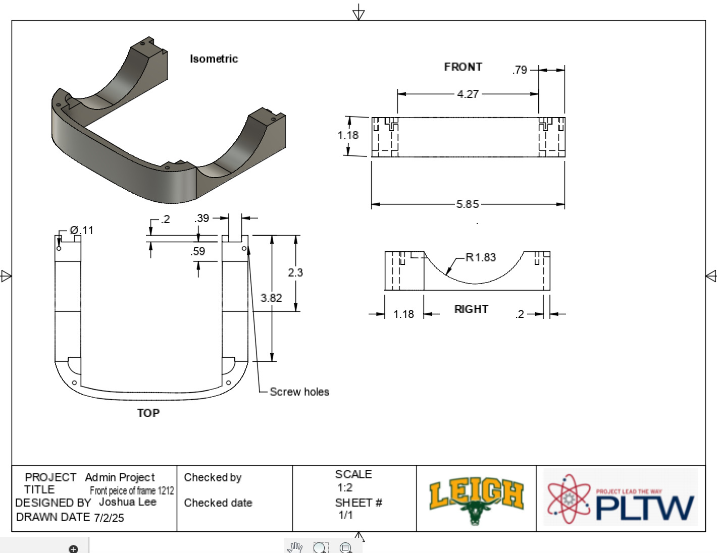 Figure 10: Design drawing of the front part of the frame
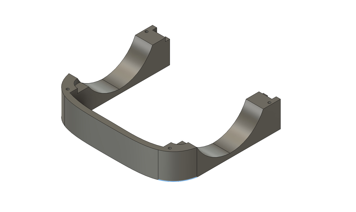
Figure 11: This is the front section of my frame that will go on my robot. The arcs on the side give the wheels space to turn, and the joints on the end help connect the front and back sections.
Frame installed on the robot
Second Milestone
Description
Since my first milestone, I have worked on the Bluetooth connection and the code that allows the Bluetooth to control the DC motors. I was able to connect the Bluetooth modules to the motors, and now, by simply tilting the second Bluetooth module, I can move the robot forward, backward, right, and left as demonstrated in the code at the bottom of the website. The accelerometer in the MPU-6050 sends the acceleration data to the NANO, which converts the raw acceleration data to AccX, AccY, and AccZ. This data is sent over to the HC-O5 on the robot and used to determine if the robot should stop, turn right, turn left, move forward, or move backward using if-else statements.. During this process, I was surprised by how much easier it became to debug my code once I understood it more.
Challenges
One of the biggest challenges I faced was accidentally flipping the RX and TX pin connections. Before realizing that this was the issue, I spent a lot of time changing the code and writing separate test scripts to identify the problem. When none of those worked, I finally checked the wiring and discovered that I had swapped the RX and TX pins. After correcting that, I also had to replace two dead batteries because the motors did not have enough power to start consistently. Once those two problems were fixed, the robot functioned properly.
What’s Next?
In the 3rd milestone, I will create holding structures for all my circuit boards to keep them in place, and add finishing touches such as organizing the wires and making framing for the whole robot to look aesthetically pleasing.
Flow Chart for Code
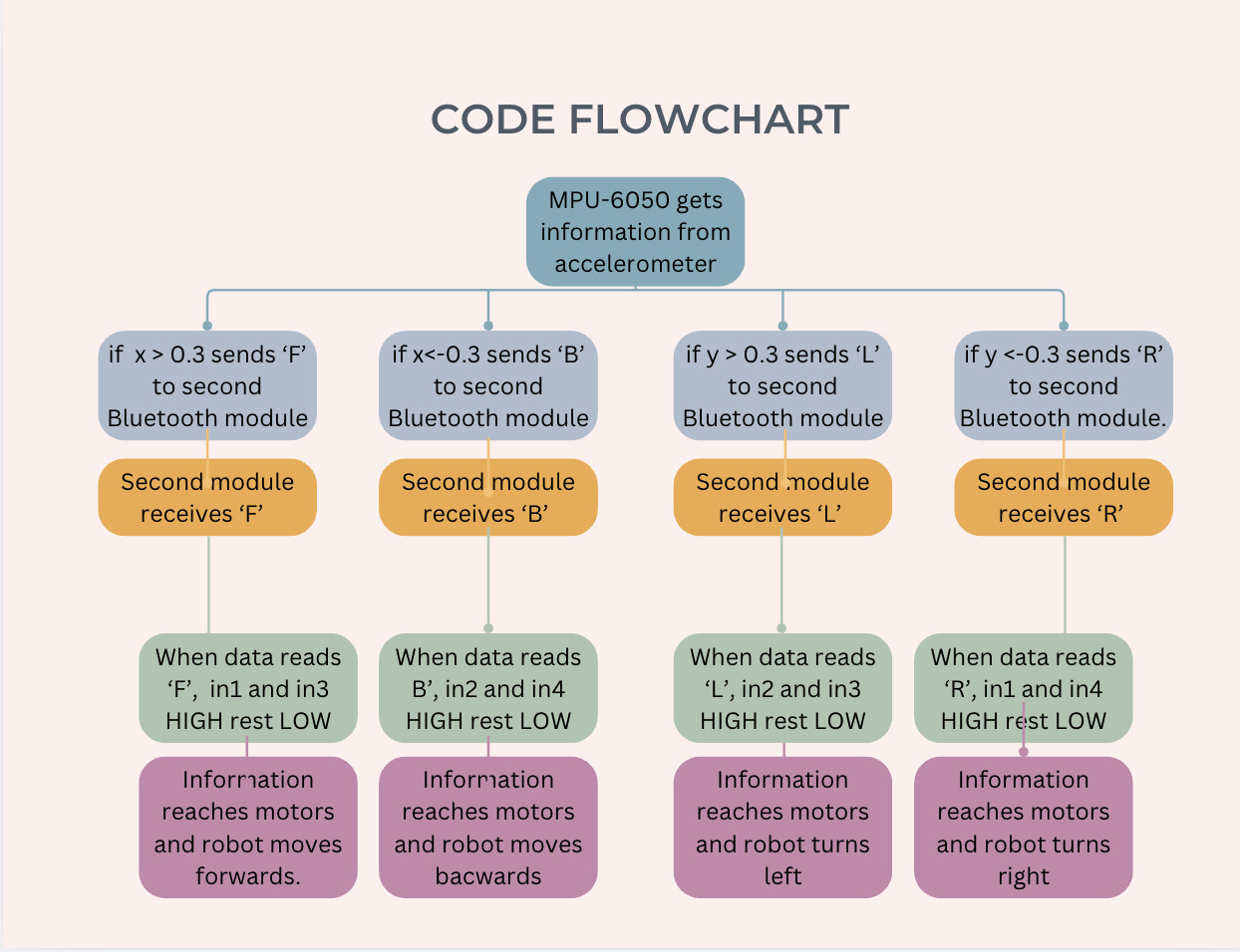
Figure 12: Flow chart of the code that connects gesture motions to motor movement
First Milestone
Description
My main project is the Gesture Controlled Robot, and I plan to finish it in this camp. The project includes two major components - the 4 DC motors for movement and the Bluetooth connections for control. These two components will work together to move the robot around and display the gesture-controlling feature. By this first milestone, I have completed the hardware for the robot along with the code that controls the motor movement. As seen in Figure 1, the hardware includes the drivetrain, Arduino UNO board, L280N board, Bluetooth receiver, and Bluetooth master. The code I implemented coded the motor movement for the robot. I did this by connecting the Arduino UNO and L280N boards to the motors, which allowed me to easily code the movement through the IN1, IN2, IN3, and IN4 ports. I have also connected the two Bluetooth modules - one master and one slave - so they are now ready to code and control the robot. The master module is seen in Figure 2, and the slave module is found in Figure 1.
Challenges
When configuring the motors for the first time, I realized that one motor on each side was spinning in the wrong direction. When debugging for the first time, I didn’t know what was wrong - the code seemed fine, and there were no errors. But then I realized that I had to physically change the motor polarity for them to move in the correct direction. So, I flipped the two sets of wires connected to the L280N board and was able to fix the motor polarity. Luckily, this robot has a DC motor that can change polarities easily, unlike other motors such as AC and single-phase.
What’s Next?
To finish this project, I have to code the Bluetooth to control the movement of my robot along with adding some modifications.
How it Works
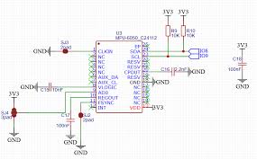
Figure 13: Diagram of the MPU-6050
The MPU-6050 is an accelerometer and gyroscope sensor. To measure the acceleration, the accelerometer detects the force exerted on a spring system located inside the MPU-6050. When the accelerometer experiences acceleration, the mass will lag behind due to its inertia, causing a deflection of the spring. This deflection is proportional to the acceleration levels the MPU experiences. In my project, I took the acceleration data from the MPU and converted it to AccX, AccY, and AccZ (which are the levels of acceleration on the x, y, z axes). Using this data, I was able to use if-else statements (code at the bottom of the portfolio) to determine if the robot moved forward, backward, right, or left.
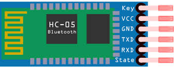
Figure 14: Close-up of a Bluetooth HC-O5 module
The HC-05 Bluetooth module is a wireless communication device that uses serial (UART) signals to send and receive data between a microcontroller (like an Arduino UNO) and another Bluetooth device, such as a smartphone or computer. It works like a wireless version of a serial cable, allowing two devices to “talk” to each other over Bluetooth instead of through physical wires. When connected, the HC-05 can receive data through its RX pin and send data through its TX pin. The module operates in either master or slave mode, and it can be reconfigured using AT commands when placed in command mode. This allows you to change things like its name, PIN, and connection settings. For example, in my project, I used an HC-05 on my robot to allow wireless control through a controller.
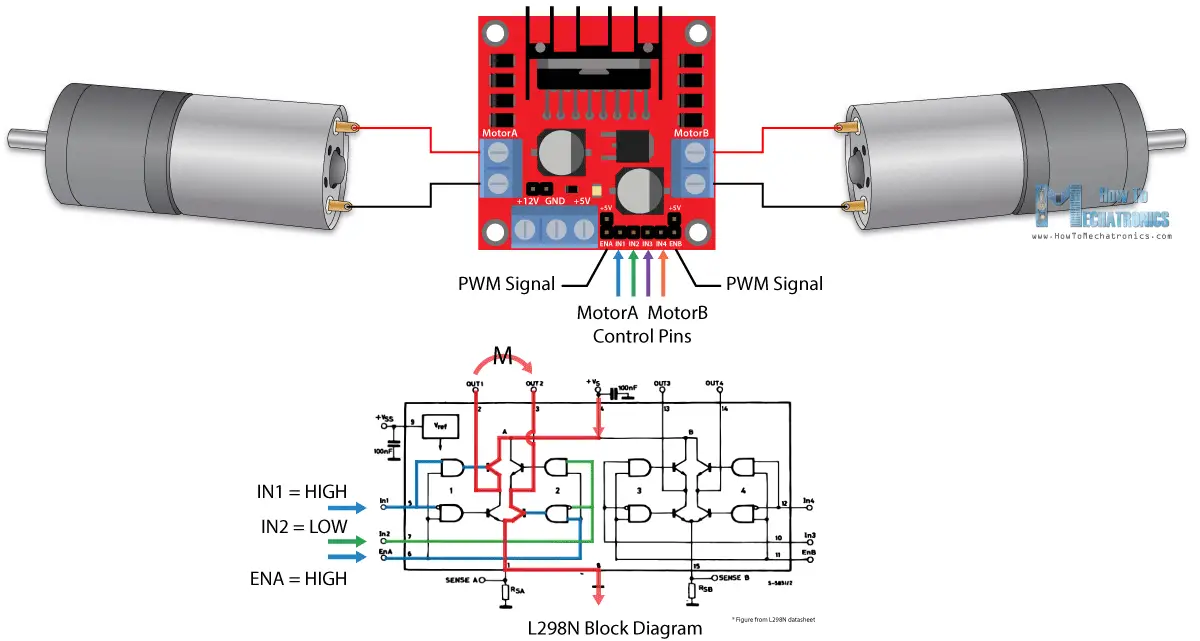
Figure 15: Diagram of the L280N in the robot
The L280N has two H-Bridges, which are electric circuits that allow a DC motor to be driven in both forward and backward directions. This is accomplished by the four switches on the outer parameters of the circuit board. By controlling which switches are on and off, you can easily control the direction the motors spin. For example, if the IN1 and IN3 switches were set to high, and the IN2 and IN4 switches were set to low, then the motors would move forward. Without the help of the L280N, which changes the way the current flows to easily change the polarity of the motor, you would have to manually change the polarity of the DC motor to change the direction it’s spinning. I used an L280N in my robot to control the direction of the four DC motors on the drivetrain and connect the batteries to all the other hardware. Each H-bridge is connected to one pair of motors on each side, which is seen in Figure 3 above.
Figure 16: Diagram of an Arduino UNO used in the project
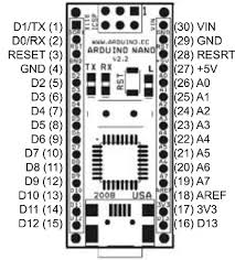
Figure 17: Diagram of an Arduino Nano used in this project
Microcontrollers
In my project, I have two different microcontrollers - The Arduino UNO and Arduino NANO. The difference between the two is that the NANO is breadboard-friendly, which allows it to be portable, while the UNO is much larger and has more ports. The purpose of these microcontrollers is to process the code into the other components. They act like small specialized computers that allow the robot to function without being plugged into a laptop.
Schematics of the Hardware on my Gesture-Controlled Robot
Figure 18: Schematic of the Gesture Controlled Robot’s hardware - Arduino UNO, L280N, 4 DC motors, 4 AAA batteries, and HC-O5
Figure 19: Schematic of Bluetooth sending module (gauntlet) - HC-O5, MPU 6050, and Arduino NANO
Starter Project (Milestone)
Description
For my starter project, I chose to do the RGB slider. The reason for this is that I wanted to design headlights and taillights for my gesture-controlled robot that turn on when I move forward or backward. This project gave me experience in coding LEDs, which will help me make these modifications to my final project. The RGB slider is a small board that contains three RGB sliders, an LED, and a USB-C port. The three RGB sliders control an LED. Three colors - blue, red, and green - are mixed to display different colors on the LED. As you slide the sliders up and down, the strength of the color increases or decreases. There are almost an infinite number of color combinations I can use to light up my LED, and everything on the board is powered by a USB-C that is connected to my laptop.
Challenges
Challenges that I faced while making the RGB slider included soldering too much and soldering the whole board upside down. As easy as this project was, I forgot to ask my instructor if I was doing everything on the right side. This made me have to redo the entire RGB slider on the other side of the board. To do this, I unsoldered everything and resoldered it on the other side.
What’s Next?
The next thing I will do is create my main project - the gesture-controlled robot.
Bill of Materials
| Part | Note | Price | Link |
|---|---|---|---|
| Arduino UNO | Used to interpret the information from HC-O5 and send it to the L280N for motor movement | $27.60 | Link |
| L280N | Used to move the dc motors | $2.50 | Link |
| Robot drivetrain kit | Used for the 4 DC motors, wheels, and base | $24.54 | Link |
| Arduino NANO | Used to interpret informationn from then MPU-6050 and send to the HC-O5 | $25.70 | Link |
| HC-O5 | Used for wirless communication | $9.99 | Link |
| MPU-6050 | Used for its accelerometer, and it reads the gestures | $1.39 | Link |
| Breadboard | Used to connect circuit boards and HC-O5’s together with help of wires | $0.99 | Link |
| Wires | Used to connect everthing | $0.99 | Link |
| Robotic Arm Kit | I used this as my modification and it is mounted on the top of my gesture-controlled robot | $48.99 | Link |
| 4 MG90S servos | used in my robotic arm joints | $13.99 | Link |
| AA battery holders (5 batteries in each holder) | used to power robotic arm and gesture-controlled robot | $7.99 | Link |
Sources
-
https://howtomechatronics.com/tutorials/arduino/arduino-dc-motor-control-tutorial-l298n-pwm-h-bridge/
-
https://docs.cirkitdesigner.com/component/d1439f73-3af9-06c4-8e23-235ee200a5f1/hc-05-bluetooth-module
-
https://www.geeksforgeeks.org/electronics-engineering/overview-of-the-arduino-uno-components/
-
https://www.researchgate.net/figure/Arduino-Nano-hardware-circuit-diagram_fig4_335065396
-
https://components101.com/motors/mg90s-metal-gear-servo-motor
Appendix
Joystick Data Sending Code
#include <SoftwareSerial.h>       // installs the softwwareserial.h and servo.h libraries
#include <Servo.h>

SoftwareSerial Bluetooth(2, 3);   // Sets the RX TX pins (2 TX, 3 RX)

                                  // Servo objects
Servo servobase;
Servo servobody;
Servo servoneck;
Servo servohead;

                                  // current and target positions
float basePos = 80;
float bodyPos = 90;
float neckPos = 90;
float headPos = 90;

int baseTarget = 80;
int bodyTarget = 90;
int neckTarget = 90;
int headTarget = 90;

                                  // default servo positions
const int baseHome = 80;
const int bodyHome = 90;
const int neckHome = 90;
const int headHome = 90;

// Inactivity timer
unsigned long lastCommandTime = 0;
const unsigned long timeoutDuration = 5000;  // 5 seconds

char data;                                   // sets data variable as a char variable

void setup() {
  Serial.begin(9600);             // starts checking in buffer zone for data
  Bluetooth.begin(9600);          // in bluetooth and serial mode


  servobase.attach(4);            // gives each class a pin and attaches servos
  servobody.attach(5);
  servoneck.attach(6);
  servohead.attach(7);

                                  // moves to initial positions
  servobase.write(basePos);
  servobody.write(bodyPos);
  servoneck.write(neckPos);
  servohead.write(headPos);

  lastCommandTime = millis();  // starts timer
}

void loop() {
  // Check for Bluetooth commands
  if (Bluetooth.available()) {        // checks if bluetooth data/connection is availble
    data = Bluetooth.read();          // sets definiton for data to bluetooth.read
    Serial.print("Received: ");       // serial prints recived
    Serial.println(data);             // prints the data
    lastCommandTime = millis();


    if (data == 'F') bodyTarget = constrain(bodyTarget + 10, 0, 180);       // if certain data is sent then
    else if (data == 'B') bodyTarget = constrain(bodyTarget - 10, 0, 180);  // the servo coresponding with the information will move 10 degrees
    else if (data == 'R') baseTarget = constrain(baseTarget + 10, 0, 180);  // forwards or backwards
    else if (data == 'L') baseTarget = constrain(baseTarget - 10, 0, 180);
    else if (data == 'O') headTarget = constrain(headTarget + 10, 0, 180);
    else if (data == 'C') headTarget = constrain(headTarget - 10, 0, 180);
    else if (data == 'U') neckTarget = constrain(neckTarget + 10, 0, 180);
    else if (data == 'D') neckTarget = constrain(neckTarget - 10, 0, 180);
  }

                                              // for smooth transition toward target positions
  basePos += (baseTarget - basePos) * 0.1;
  bodyPos += (bodyTarget - bodyPos) * 0.1;
  neckPos += (neckTarget - neckPos) * 0.1;
  headPos += (headTarget - headPos) * 0.1;

                                              // writing (over bluetooth) smoothed positions to servos
  servobase.write((int)basePos);
  servobody.write((int)bodyPos);
  servoneck.write((int)neckPos);
  servohead.write((int)headPos);

                                              //if no input is detected for 5 secs the servos will reset
  if (millis() - lastCommandTime > timeoutDuration) {
    baseTarget = baseHome;
    bodyTarget = bodyHome;
    neckTarget = neckHome;
    headTarget = headHome;

    Serial.println("No input — resetting to default position."); // serial prints no input dected
    lastCommandTime = millis();                                   // prevents repeated resets
  }

  delay(20);                                            // delay for smoothness in controls
} ```end
Robotic Arm Reciver Code for Modifcations
#include <SoftwareSerial.h>       // installs the softwwareserial.h and servo.h libraries
#include <Servo.h>

SoftwareSerial Bluetooth(2, 3);   // Sets the RX TX pins (2 TX, 3 RX)

                                  // Servo objects
Servo servobase;
Servo servobody;
Servo servoneck;
Servo servohead;

                                  // current and target positions
float basePos = 80;
float bodyPos = 90;
float neckPos = 90;
float headPos = 90;

int baseTarget = 80;
int bodyTarget = 90;
int neckTarget = 90;
int headTarget = 90;

                                  // default servo positions
const int baseHome = 80;
const int bodyHome = 90;
const int neckHome = 90;
const int headHome = 90;

// Inactivity timer
unsigned long lastCommandTime = 0;
const unsigned long timeoutDuration = 5000;  // 5 seconds

char data;                                   // sets data variable as a char variable

void setup() {
  Serial.begin(9600);             // starts checking in buffer zone for data
  Bluetooth.begin(9600);          // in bluetooth and serial mode


  servobase.attach(4);            // gives each class a pin and attaches servos
  servobody.attach(5);
  servoneck.attach(6);
  servohead.attach(7);

                                  // moves to initial positions
  servobase.write(basePos);
  servobody.write(bodyPos);
  servoneck.write(neckPos);
  servohead.write(headPos);

  lastCommandTime = millis();  // starts timer
}

void loop() {
  // Check for Bluetooth commands
  if (Bluetooth.available()) {        // checks if bluetooth data/connection is availble
    data = Bluetooth.read();          // sets definiton for data to bluetooth.read
    Serial.print("Received: ");       // serial prints recived
    Serial.println(data);             // prints the data
    lastCommandTime = millis();


    if (data == 'F') bodyTarget = constrain(bodyTarget + 10, 0, 180);       // if certain data is sent then
    else if (data == 'B') bodyTarget = constrain(bodyTarget - 10, 0, 180);  // the servo coresponding with the information will move 10 degrees
    else if (data == 'R') baseTarget = constrain(baseTarget + 10, 0, 180);  // forwards or backwards
    else if (data == 'L') baseTarget = constrain(baseTarget - 10, 0, 180);
    else if (data == 'O') headTarget = constrain(headTarget + 10, 0, 180);
    else if (data == 'C') headTarget = constrain(headTarget - 10, 0, 180);
    else if (data == 'U') neckTarget = constrain(neckTarget + 10, 0, 180);
    else if (data == 'D') neckTarget = constrain(neckTarget - 10, 0, 180);
  }

                                              // for smooth transition toward target positions
  basePos += (baseTarget - basePos) * 0.1;
  bodyPos += (bodyTarget - bodyPos) * 0.1;
  neckPos += (neckTarget - neckPos) * 0.1;
  headPos += (headTarget - headPos) * 0.1;

                                              // writing (over Bluetooth) smoothed positions to servos
  servobase.write((int)basePos);
  servobody.write((int)bodyPos);
  servoneck.write((int)neckPos);
  servohead.write((int)headPos);

                                              //If no input is detected for 5 seconds the servos will reset
  if (millis() - lastCommandTime > timeoutDuration) {
    baseTarget = baseHome;
    bodyTarget = bodyHome;
    neckTarget = neckHome;
    headTarget = headHome;

    Serial.println("No input — resetting to default position."); // serial prints no input dected
    lastCommandTime = millis();                                   // prevents repeated resets
  }

  delay(20);                                            // delay for smoothness in controls
}
Bluetooth to Motor movement Code for Milestone 2
// Bluetooth to motor movement code - robot

#include <SoftwareSerial.h>        //includes library softwareserial

char data;                         //introduces variable DATA

int enA = 5;                       // sets motor pins
int in1 = 6;                       // in1, right top motor, in2 right bottom motor, in3, left top motor, in4, left bottom
int in2 = 7;
int in3 = 8;
int in4 = 9;
int enB = 10;


SoftwareSerial Bluetooth(2, 3);   //(TX , RX)

void setup() {
  Serial.begin(9600);             //begins serial monitor and sets 9600 baud
  Bluetooth.begin(9600);          //begins bluetooth search and sets 9600 baud

  pinMode(enA, OUTPUT);
  pinMode(in1, OUTPUT);           // Sets all ports as outputs
  pinMode(in2, OUTPUT);
  pinMode(in3, OUTPUT);
  pinMode(in4, OUTPUT);
  pinMode(enB, OUTPUT);
}

void loop() {

  if (Bluetooth.available()) {    // checks bluetooth buffezone
    data = Bluetooth.read();      // sets variable DATA as bluetooth.read
    Serial.println(data);         // prints said DATA

   if (data == 'F') {             //If the data is F, B, L, R, or S, the motor movement aligns
      driveForward();
    } else if (data == 'B') {
      driveBackward();
    } else if (data == 'L') {
      turnLeft();
    } else if (data == 'R') {
      turnRight();
    } else {
      stopMotors();
    }
  }
}

void driveForward() {
  digitalWrite(in1, HIGH); digitalWrite(in2, LOW); analogWrite(enA, 255);  //Motor movement from in1,2,3,4, pins HIGH or LOW to deterime direction
  digitalWrite(in3, HIGH); digitalWrite(in4, LOW); analogWrite(enB, 255);
}

void driveBackward() {
  digitalWrite(in1, LOW); digitalWrite(in2, HIGH); analogWrite(enA, 255);
  digitalWrite(in3, LOW); digitalWrite(in4, HIGH); analogWrite(enB, 255);
}

void turnRight() {
  digitalWrite(in1, HIGH); digitalWrite(in2, LOW); analogWrite(enA, 255);
  digitalWrite(in3, LOW); digitalWrite(in4, HIGH); analogWrite(enB, 255);
}

void turnLeft() {
  digitalWrite(in1, LOW); digitalWrite(in2, HIGH); analogWrite(enA, 255);
  digitalWrite(in3, HIGH); digitalWrite(in4, LOW); analogWrite(enB, 255);
}

void stopMotors() {
  digitalWrite(in1, LOW); digitalWrite(in2, LOW); analogWrite(enA, 0);
  digitalWrite(in3, LOW); digitalWrite(in4, LOW); analogWrite(enB, 0);
}

// end
Accelerometer Data Code for Milestone 2
//Accelerometer Data code - gauntlet code

#include <Wire.h>              // library for I2C communication
#include <SoftwareSerial.h>    // library to use software-defined serial communication

// Set up Bluetooth communication on pins 2 (TX) and 3 (RX)
SoftwareSerial Bluetooth(2, 3); // bluetooth module connected to digital pins 2 and 3

const int MPU = 0x68;          // address of the MPU6050 accelerometer
float AccX, AccY, AccZ;        // variables to store the acceleration values
char lastCommand = ' ';        // to store the last command sent

void setup() {
  Wire.begin();                // starts IC2 communication
  Serial.begin(9600);          // starts Serial monitor communication
  Bluetooth.begin(9600);       // start Bluetooth communication

  // wakes up the MPU6050 by writing 0
  Wire.beginTransmission(MPU);
  Wire.write(0x6B);            // accesses the power
  Wire.write(0);               // sets it to 0 to wake up the MPU6050
  Wire.endTransmission(true);
}

void loop() {
  // request accelerometer data starting from register 0x3B
  Wire.beginTransmission(MPU);
  Wire.write(0x3B);
  Wire.endTransmission(false);
  Wire.requestFrom(MPU, 6, true); // requests 6 bytes (X, Y, Z axes)

  // Combines high and low bytes to get raw acceleration data
  int16_t rawX = Wire.read() << 8 | Wire.read();
  int16_t rawY = Wire.read() << 8 | Wire.read();
  int16_t rawZ = Wire.read() << 8 | Wire.read();

  // Convert raw values to accx, y, z
  AccX = rawX / 16384.0;
  AccY = rawY / 16384.0;
  AccZ = rawZ / 16384.0;

  char command; // Command to be sent based on tilt

  // Decide which direction to move based on tilt:
  if (AccX > 0.3)
    command = 'F';            // Tilt forward - Forward
  else if (AccX < -0.3)
    command = 'B';            // Tilt backward - Backward
  else if (AccY > 0.3)
    command = 'L';            // Tilt left -  Left
  else if (AccY < -0.3)
    command = 'R';            // Tilt right - Right
  else
    command = 'S';            // No tilt - Stop

  // Only send the command if it has changed since last time
  if (command != lastCommand) {
    Bluetooth.write(command);  // send the command to Bluetooth module
    Serial.println(command);   // also print to serial monitor for debugging
    lastCommand = command;     // update the last command
  }

  delay(100);  // Small delay to reduce how often data is sent (every 100 ms)
}
// end
Motor Movement code for Milestone 1
// Motor movement code

int enA = 5; // sets motor pins
int in1 = 6;
int in2 = 7;
int in3 = 8;
int in4 = 9;
int enB = 10;

void driveforward(){
  digitalWrite(in1, HIGH); //sets motors to drive forwards
  digitalWrite(in2, LOW);
  analogWrite(enA, 255);
  digitalWrite(in3, HIGH);
  digitalWrite(in4, LOW);
  analogWrite(enB,255);
  delay(1000);
}

void drivebackward(){
  digitalWrite(in1, LOW);  //sets motors to drive backwards
  digitalWrite(in2,HIGH);
  analogWrite(enA,255);
  digitalWrite(in3, LOW);
  digitalWrite(in4, HIGH);
  analogWrite(enB,255);
  delay(1000);
}


void stop(){
  digitalWrite(in1, LOW); //sets motors to LOW or stop
  digitalWrite(in2, LOW);
  digitalWrite(in3, LOW);
  digitalWrite(in4, LOW);
  delay(1000);
}


void setup(){
  Serial.begin(9600);
  pinMode(enA, OUTPUT); // setting all pins to OUTPUTS
  pinMode(in1, OUTPUT);
  pinMode(in2, OUTPUT);
  pinMode(in3, OUTPUT);
  pinMode(in4, OUTPUT);
  pinMode(enB, OUTPUT);

}

void loop(){

  driveforward();
  stop();
  drivebackward();
  stop();

}